01 / Short answer
At the same power, 24 V usually reduces conductor current but does not remove voltage drop. Separate the data and power paths, calculate the maximum load and protect every branch before testing full brightness.
Anyone planning a low-voltage WLED run
CHECKPOINT / 01
Define the electrical boundaries before buying
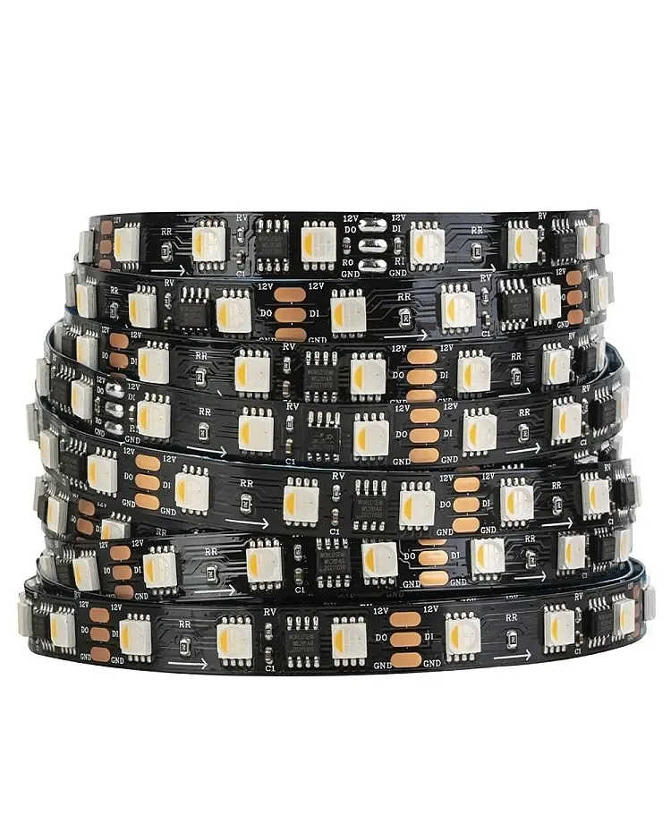
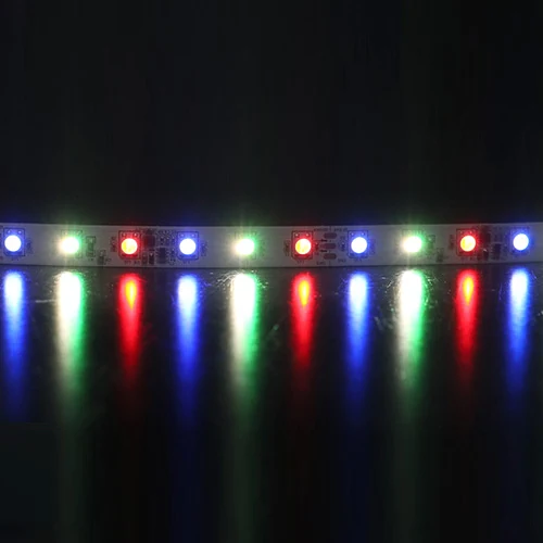
Record the strip nominal voltage, exact LED IC, data input and direction, color order, pixel or group count, energized length, controller position and every planned injection point. Separate the WLED data path from the LED power path: controller protocol support does not prove compatibility with a specific IC or variant.
- Measure and record voltage at the supply output, not only the adapter label.
- Keep the data-direction arrow visible on every section.
- Treat the controller, supply, cable and strip as separate limits.
CURRENT PRODUCT RECORDS
24 V WS2814 RGBW addressable LED strip View productCHECKPOINT / 02
Calculate maximum load and leave headroom
Use the declared watts per metre for the exact variant and multiply it by the length that can be energized at the same time. Calculate from full white or the highest-current channel combination, not the average brightness of a scene. Divide watts by 24 V to estimate current, then check the supply, controller, connectors, cable and fuses as separate limits. Supply headroom is a starting point, not a thermal test.
- Use the available maximum load when the documentation gives no more precise condition.
- Include energized sections, injection cables and contact losses in the plan.
- Do not use a constant-current source for a constant-voltage strip.
load_w = watts_per_m * energized_length_m
current_a = load_w / voltage_v
supply_w >= load_w * 1.20
record: ic + data_direction + color_order + pixel_count
CURRENT PRODUCT RECORDS
24 V WS2814 RGBW addressable LED strip View productCHECKPOINT / 03
Use 24 V without ignoring voltage drop
At the same power, a 24 V strip needs less current than a 12 V or 5 V strip, which can make long runs easier to plan. Copper resistance, total round-trip length, connectors, cable cross-section and current still create voltage drop. Check the cut interval and pixel grouping as well: lower current is not a promise of unlimited length.
- Measure voltage at the supply end and the far strip end under full white.
- Repeat the measurement for each branch with the final connector installed.
- If the far end shifts color, flickers or heats up, stop expanding and correct the path.
CURRENT PRODUCT RECORDS
24 V WS2814 RGBW addressable LED strip View productCHECKPOINT / 04
Distribute power and protect every branch
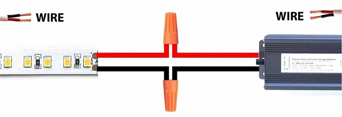
Plan power injection at the points required by length and voltage drop. Size the main fuse for the supply, and add branch protection near the distribution point when an individual cable or connector needs a lower limit. Size cable, terminals, connectors and pigtails for their real current; preserve polarity, the common ground required by the controller and service access. A fuse does not correct an undersized cable: it limits energy during a fault.
- Split long branches instead of hiding the whole load behind a small connector.
- Label voltage, polarity, fuse, cable size, destination and length on every branch.
- Keep mains work separate from the low-voltage assembly and follow local requirements.
CURRENT PRODUCT RECORDS
24 V WS2814 RGBW addressable LED strip View productCHECKPOINT / 05
Commission the real load
Power the controller and shortest strip section first. Add branches one at a time and check data, full white, transitions, temperature, voltage at both ends, controller restart and recovery after network loss. Record the target firmware, IC, color order, brightness limit, supply, fuses, cables and measured result. If the length, enclosure or strip variant changes, repeat the review.
- Test a safe white-light scene before intense effects.
- Check behavior after power-off and power-on.
- Leave a known manual recovery method for when the network or automation is unavailable.
CURRENT PRODUCT RECORDS
24 V WS2814 RGBW addressable LED strip View productVISUAL REFERENCES
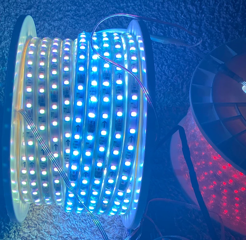
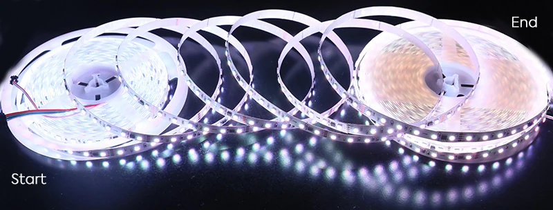
See the layers before you specify the parts.
FAILURE MODES
What usually goes wrong
- The supply is chosen from average brightness instead of the maximum full-white load.
- 24 V is assumed to eliminate voltage drop, so the far end is never measured.
- The data path and power path are documented as if they were one circuit.
- The supply is protected, but a thin branch, pigtail or connector has no suitable limit.
- The installation is approved from a short sample without retesting after length or injection is added.
TECHNICAL BASIS / VERSION
Keep the decision current
This guide is maintained as a versioned technical record. Recheck the current protocol documentation and the exact product revision before using it in a production installation.
Confirm the selected voltage, light engine, driver, controller, firmware and installation conditions against the product record and project brief.
FAQ / QUICK ANSWERS
Common questions about this lighting setup
Is 24 V always better than 5 V or 12 V for WLED?
No. At the same power, 24 V usually reduces current and can simplify long runs, while 5 V can offer a finer cut interval for small addressable details. Choose from length, cut accuracy, pixel grouping, IC, controller path and measured voltage drop.
Can I size the supply from average brightness?
Not for the design limit. Use the exact variant’s maximum declared load, or the highest-current state the system can request, add practical headroom, and check temperature, connectors, cable and fuses. Average brightness describes a scene, not the required peak capacity.
What should I record before configuring WLED?
Record voltage, IC, data input and direction, color order, pixel or group count, energized length, controller, target firmware, supply, injection points, fuses, cables and the full-white test result. Do not claim compatibility from the WLED name or a similar connector alone.
READING LIST
Reference points used for this guide
The page is rewritten for LumaCircuit readers. These references establish the original topic or technical context; they do not replace an exact product review or a LumaCircuit test record.
- Reference article / powering a 24 V WLED installation