01 / Short answer
0-10 V is a low-voltage analog control signal, not a replacement for the LED driver output. A complete system needs a compatible dimmer, control pair, driver and light engine, with the mains and DC load paths kept separate and the low-end behavior verified.
Lighting designers and installers specifying 0-10 V control for compatible LED drivers and strip systems
CHECKPOINT / 01
Separate the signal from the light power
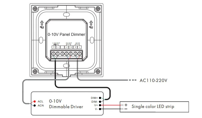
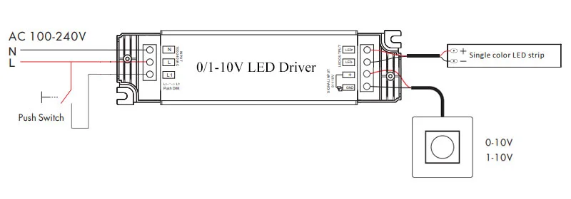
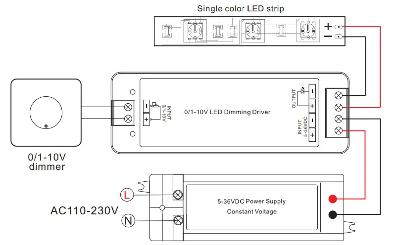
In a 0-10 V system, the control device communicates a voltage signal to a driver that is designed to interpret it. The driver still receives its required mains input and produces the output needed by the LED strip or fixture. A two-wire dimming pair is therefore not a substitute for the supply conductors. Draw the control pair and power path as two different circuits before choosing cable or terminals.
- Confirm the driver explicitly accepts 0-10 V control.
- Keep the signal pair identified and separated from the load output.
- Do not feed 0-10 V into a raw LED strip or an unrelated PWM input.
CURRENT PRODUCT RECORDS
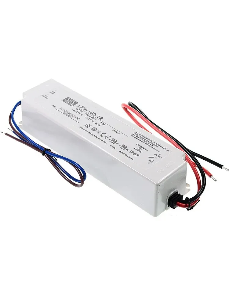
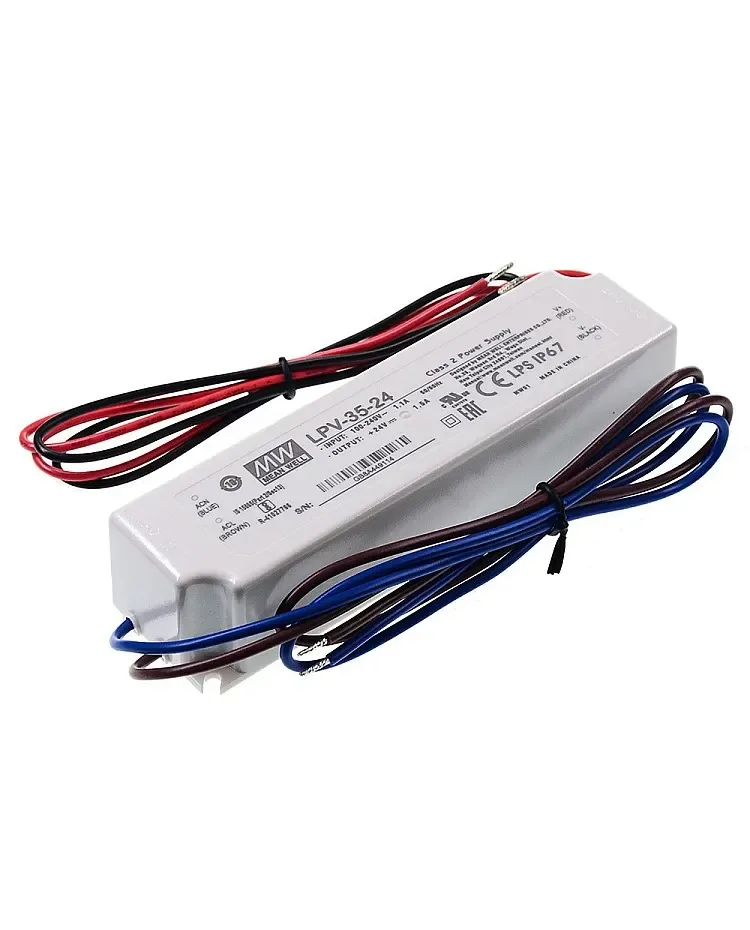
100 W IP67 LED power supply View product 35 W waterproof LED power supply View productCHECKPOINT / 02
Check 0-10 V versus 1-10 V behavior
A 0-10 V interface may use a lower signal to represent off or minimum output, while a 1-10 V interface commonly retains a nonzero minimum. The actual driver and dimmer determine whether the lowest signal produces off, a low level or a fault. If complete shutoff is required, the design may need a relay, enable input or separate switching method that is explicitly compatible with the driver.
- Record the minimum and maximum control voltage in the system handoff.
- Confirm whether the dimmer sources or sinks the signal current.
- Test the off state instead of assuming zero volts means no light.
CHECKPOINT / 03
Match the driver, dimmer and load
A 0-10 V wall device can be rated for a particular number or type of drivers, while the driver can have limits for signal range, wire distance and load. The LED strip must match the driver output voltage and current, and any profile or controller on the DC side must remain within its own limits. Do not infer compatibility from a product category label; use the exact driver manual and control wiring.
- Check driver input, output, dimming method and minimum load.
- Check the dimmer signal capacity and the number of connected drivers.
- Keep the LED load and control signal ratings in the same project record.
CURRENT PRODUCT RECORDS
35 W waterproof LED power supply View product 100 W IP67 LED power supply View productCHECKPOINT / 04
Plan the low-end and wiring route
The useful dimming range can narrow near the bottom because different drivers and light engines respond differently to small control changes. Long control cables add routing and interference concerns, while the DC load cable has its own voltage-drop problem. Route, label and terminate both paths deliberately. If a project needs smooth low-level output or a defined off state, make that a sample acceptance criterion.
signal_v = measure_control_pair()
output = observe_driver(signal_v)
accept = min_level <= target && off_state == required_behavior
CURRENT PRODUCT RECORDS
35 W waterproof LED power supply View productCHECKPOINT / 05
Commission with a meter and the real load
Before energizing, verify the driver and dimmer terminals against their manuals. Measure the control signal at minimum, middle and maximum settings, then observe the LED output, flicker, color stability and restart behavior. Repeat with the full number of drivers and the final cable route. Record signal polarity, measured range, minimum output, off method, driver variant and the exact strip or fixture connected.
- Do not judge the system with an unloaded driver or a substitute strip.
- Check the signal at the farthest driver when several are connected.
- Keep a fallback manual control or service disconnect where the project needs it.
CURRENT PRODUCT RECORDS
100 W IP67 LED power supply View product 35 W waterproof LED power supply View productVISUAL REFERENCES
See the layers before you specify the parts.
FAILURE MODES
What usually goes wrong
- The 0-10 V pair is mistaken for the LED DC output.
- A 1-10 V dimmer and a 0-10 V driver are connected without checking their minimum behavior.
- The strip or fixture is connected to a driver whose output voltage or dimming interface is different.
- Several drivers are connected beyond the dimmer signal capacity or cable guidance.
- The system is approved from the wall control feel without measuring signal range and the real light output.
TECHNICAL BASIS / VERSION
Keep the decision current
This guide is maintained as a versioned technical record. Recheck the current protocol documentation and the exact product revision before using it in a production installation.
Confirm the selected voltage, light engine, driver, controller, firmware and installation conditions against the product record and project brief.
FAQ / QUICK ANSWERS
Common questions about this lighting setup
Does 0-10 V power an LED strip?
No. It is a control signal. The LED strip still needs a compatible driver or power supply that converts the required input into the correct low-voltage output.
Does zero volts always turn the light off?
No. The actual minimum can depend on whether the system is 0-10 V or 1-10 V and on the driver. A separate switching or enable method may be needed for a reliable off state.
Can I connect any 0-10 V dimmer to any LED driver?
No. Check signal sourcing or sinking, minimum load, driver interface, cable guidance, polarity and the number of connected drivers in the exact manuals.
READING LIST
Reference points used for this guide
The page is rewritten for LumaCircuit readers. These references establish the original topic or technical context; they do not replace an exact product review or a LumaCircuit test record.
- Technical reference / 0-10 V signal, driver and commissioning