01 / Short answer
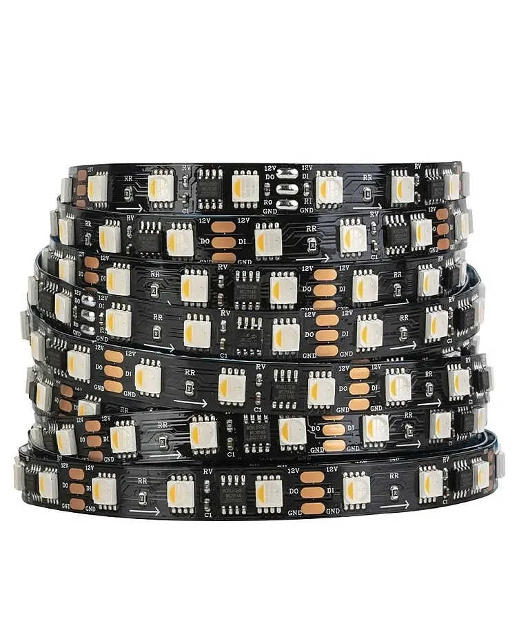
A 24 V addressable label describes the input supply, not the resolution or a ready-made WLED profile. Identify the internal grouping, IC, data direction and power path before scaling the effects.
Builders choosing a higher-voltage addressable strip for architectural runs, pixels or effect lighting
CHECKPOINT / 01
Read what 24 V addressable actually means
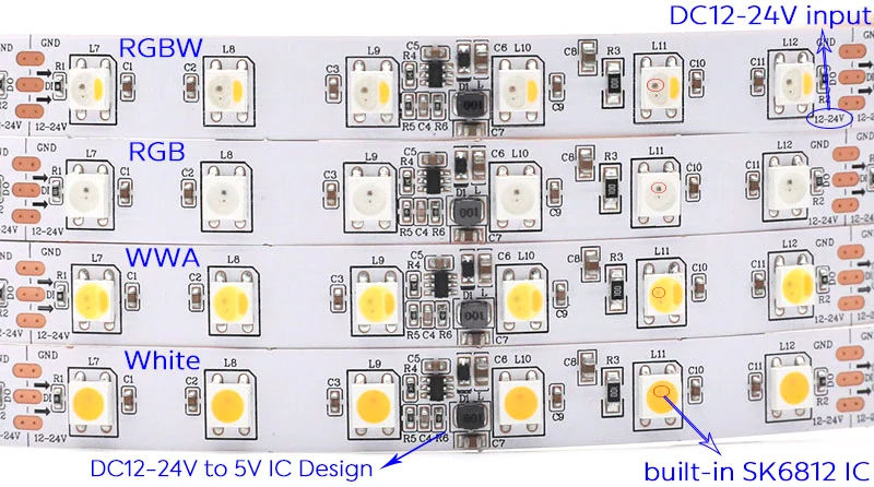
A 24 V strip may use local conversion or series LED groups behind each control IC. The controller can address groups of LEDs rather than every visible emitter, so the product may be individually controllable at a segment or pixel-group level without making every diode independent. Ask for the controllable unit, cut interval, watts per metre and data protocol instead of relying on the word individually.
- Input voltage, LED grouping and control resolution are separate product fields.
- Count pixels or controllable groups, not just the number of visible LEDs.
- Keep the source 24 V example separate from any current LumaCircuit variant record.
CURRENT PRODUCT RECORDS
24 V WS2814 RGBW addressable LED strip View productCHECKPOINT / 02
Compare external and built-in control electronics
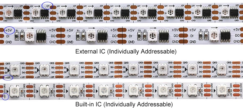
An external IC arrangement may place the control component away from the LED group, while a built-in arrangement integrates it into the strip section. That construction changes cut marks, pixel resolution, fault behavior and the information needed by the controller. Photograph the first section, locate the data input and output and record the exact IC before selecting a WLED LED type.
- Write down the number of LEDs per controllable group.
- Check arrows, data-in, data-out, power and ground markings.
- Do not infer a supported IC from a three-wire or four-wire connector alone.
CURRENT PRODUCT RECORDS
24 V WS2814 RGBW addressable LED strip View productCHECKPOINT / 03
Use the voltage advantage without losing the data plan
For equal power, a higher supply voltage generally means less current in the same branch, which can make cable and injection planning easier. It does not remove connector resistance, strip voltage drop, fusing or the need for a correctly sized supply. The controller must send the exact signal format, and the strip still needs a common reference where the circuit requires it.
load_w = length_m * watts_per_m
current_a = load_w / 24
supply_w >= load_w * 1.20
data_path = exact_IC + direction + color_order
CHECKPOINT / 04
Plan injection and branch protection
Start from the declared maximum load and the longest cable distance. Use practical branch fuses, connectors and conductor sizes that match the current and installation boundary, then measure voltage at the strip under a repeatable bright state. A 24 V strip can still show color shift or a dead group when the feed, connector or far-end path is the bottleneck.
- Keep the supply end and strip end measurements in the project record.
- Separate data extensions from high-current power branches.
- Use a profile or mounting surface that supports the selected thermal load.
CHECKPOINT / 05
Prove resolution and color order on the bench
Connect the shortest known-good section, configure the identified LED type, set the pixel or group count and test solid red, green, blue and white. Then walk a single-pixel or group chase through the strip to verify the actual resolution and data direction. Save the working WLED profile with the strip variant, firmware, brightness limit, supply and wiring before installing the full run.
short_section -> solid_RGBW -> chase
verify: IC + group_count + color_order
then: restart + brightness_limit + recovery_preset
CURRENT PRODUCT RECORDS
24 V WS2814 RGBW addressable LED strip View productVISUAL REFERENCES
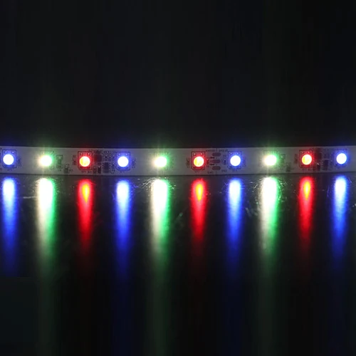
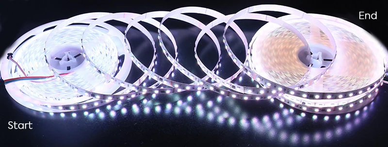
See the layers before you specify the parts.
FAILURE MODES
What usually goes wrong
- 24 V input is interpreted as one independently addressable pixel per visible LED.
- The WLED profile is chosen from voltage alone and the IC or color order is wrong.
- A higher voltage supply is used without recalculating the exact strip load and fuse branch.
- Data direction is assumed from connector shape or wire color.
- A full reel is installed before the group resolution and far-end voltage are tested.
TECHNICAL BASIS / VERSION
Keep the decision current
This guide is maintained as a versioned technical record. Recheck the current protocol documentation and the exact product revision before using it in a production installation.
Confirm the selected voltage, light engine, driver, controller, firmware and installation conditions against the product record and project brief.
FAQ / QUICK ANSWERS
Common questions about this lighting setup
Are 24 V addressable LED strips individually addressable?
Some are addressable by LED groups or segments rather than by every visible diode. Confirm the controllable unit, IC, cut interval and data protocol for the exact variant before promising pixel-level effects.
Is 24 V easier to power than 5 V?
For the same power, a 24 V branch generally carries less current, which can help with cable and injection planning. It still needs the correct supply, fuses, connectors, data path and far-end voltage check.
Can I connect any 24 V addressable strip to WLED?
No. WLED setup depends on the exact IC or supported profile, data direction, color order, channel format and controller output. Unknown chips remain to be identified and validated.
READING LIST
Reference points used for this guide
The page is rewritten for LumaCircuit readers. These references establish the original topic or technical context; they do not replace an exact product review or a LumaCircuit test record.
- Reference / 24 V addressable strip grouping, control and power