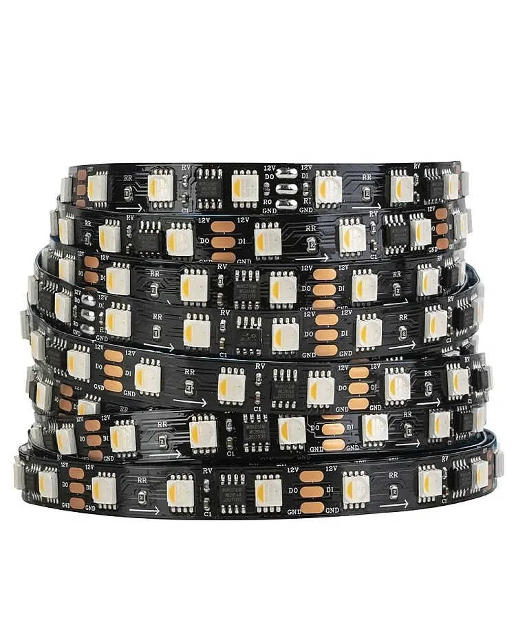
01 / Short answer
The controller is selected from the light engine, channel topology, current and control boundary. Start with the strip record, then choose how commands will reach it.
DIY builders, installers and designers choosing control hardware for static, CCT, RGBW or addressable LED strips
CHECKPOINT / 01
Name the light engine before the controller
A single-color strip, CCT strip, analog RGBW strip and addressable strip do not speak the same electrical language. The first three usually expose shared power and PWM channels; an addressable strip adds a data input, data direction, pixel or segment count and an IC profile. Write down the light engine before looking at wireless range, app features or a remote control.
- Single color: one dimmed load and a matching constant-voltage control path.
- CCT: two white channels with a controller that understands the exact channel topology.
- RGBW: red, green, blue and white channels; four-channel current matters.
- Addressable: data protocol, input direction, color order and power are separate checks.
CURRENT PRODUCT RECORDS
24 V WS2814 RGBW addressable LED strip View productCHECKPOINT / 02
Count channels, voltage and current
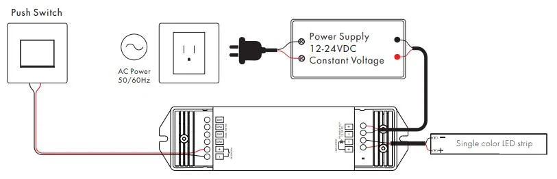
A controller output is not automatically a power supply. Match the controller voltage to the strip and check the current limit for each channel and the complete device. For a long run, calculate the strip load, then check the controller, connector, cable and fuse as individual limits. A controller with many effects can still be the wrong part if its output topology or current rating does not match the light engine.
load_w = length_m * watts_per_m
current_a = load_w / strip_voltage_v
controller_channels >= required_channels
controller_limit_a >= branch_current_a
CHECKPOINT / 03
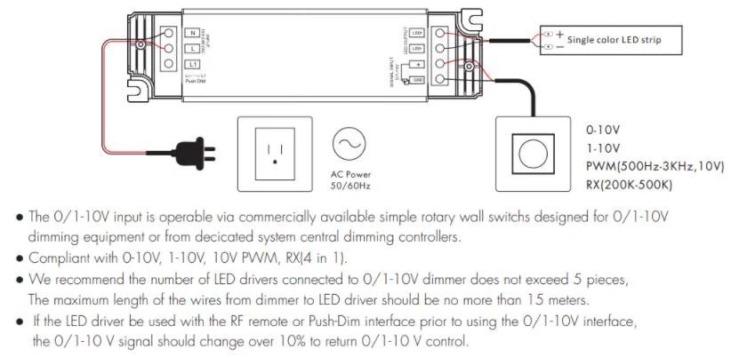
Choose the command interface from the room
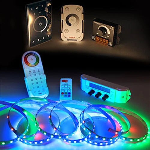
RF, Bluetooth and Wi-Fi controllers solve different control-distance and commissioning problems. A wired 0-10 V, phase-dimming, DALI or DMX path adds a different signal boundary and should be paired with the correct driver or decoder. Treat app names and protocol labels as a starting point: the selected device must document the strip type, voltage, channel count and functions you intend to use.
- Small local detail: prioritize simple, reachable control and a serviceable power path.
- Room automation: identify the local or cloud dependency before promising an integration.
- Commercial control: record the bus, decoder or driver model and who owns scene commissioning.
CHECKPOINT / 04
Addressable strips need a data profile
For an addressable product, record the exact IC family, voltage, data input, color order, pixel grouping, controller output and firmware target. WLED can be a practical local effects route when that complete path is identified, but a similar connector or a controller product name is not proof of compatibility. Keep data and power diagrams separate so a power fault is not mistaken for a signal fault.
- Connect controller data to the marked data input and share ground where the design requires it.
- Set a brightness limit from the calculated load and measured thermal path.
- Keep unknown chips as chip-to-confirm until the exact IC or documented profile is established.
CURRENT PRODUCT RECORDS
24 V WS2814 RGBW addressable LED strip View productCHECKPOINT / 05
Commission one known-good section
Start with the shortest strip section, the selected controller and a correctly sized supply. Check every channel or solid color, then test dimming, restart behavior, maximum planned brightness and the control interface from the intended location. Save the working configuration with the product variant, firmware, wiring and power measurements before scaling to the full installation.
sample -> polarity_check -> channel_test
full_load -> far_end_voltage -> temperature
record: controller + firmware + variant + result
VISUAL REFERENCES
See the layers before you specify the parts.

FAILURE MODES
What usually goes wrong
- A three-channel controller is used for a four-channel RGBW strip.
- The controller is treated as the power supply and its output limit is never checked.
- A Wi-Fi, RF or Zigbee label is treated as proof of the required local integration.
- An addressable strip is configured from a similar connector without identifying its IC and color order.
- The full installation is commissioned only after the controller and power hardware are hidden.
TECHNICAL BASIS / VERSION
Keep the decision current
This guide is maintained as a versioned technical record. Recheck the current protocol documentation and the exact product revision before using it in a production installation.
Confirm the selected voltage, light engine, driver, controller, firmware and installation conditions against the product record and project brief.
FAQ / QUICK ANSWERS
Common questions about this lighting setup
Can one controller run RGB, RGBW and CCT strips?
Only when the controller explicitly supports the selected channel topology, voltage and current. A connector that physically fits does not prove that the firmware or output stage maps the channels correctly.
Does an addressable LED strip need a separate power supply?
The controller sends data, while the strip still needs a supply matched to its voltage and maximum load. Some hardware combines functions, but the power output, branch protection and common-ground requirements must still be checked.
Is Wi-Fi better than RF for LED strip control?
Neither is universally better. Choose from control distance, local operation, automation requirements, recovery behavior and the installation environment. The light engine and power path still come first.
READING LIST
Reference points used for this guide
The page is rewritten for LumaCircuit readers. These references establish the original topic or technical context; they do not replace an exact product review or a LumaCircuit test record.
- Reference article / choosing LED strip controllers