01 / Short answer
DALI is a digital lighting system, not just a dimmer. The project needs compatible control gear, a bus, a controller, device addressing, scenes and a commissioning record that matches the installed hardware.
Lighting designers, integrators and advanced builders evaluating a DALI control path for a room or commercial installation
CHECKPOINT / 01
Understand the DALI system boundary
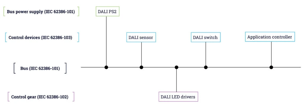
DALI provides digital commands and status communication between a control system and compatible lighting control gear. The LED fixture still needs an appropriate driver or ballast, and the bus does not replace mains wiring or the driver power stage. Treat the light engine, driver, DALI bus, application controller and input devices as separate records that must join into one working system.
- Control gear drives the light engine; the bus carries commands and device information.
- The application controller or gateway owns scenes, groups and commissioning workflow.
- Sensors and switches are input devices only when the selected system supports their role.
CURRENT PRODUCT RECORDS
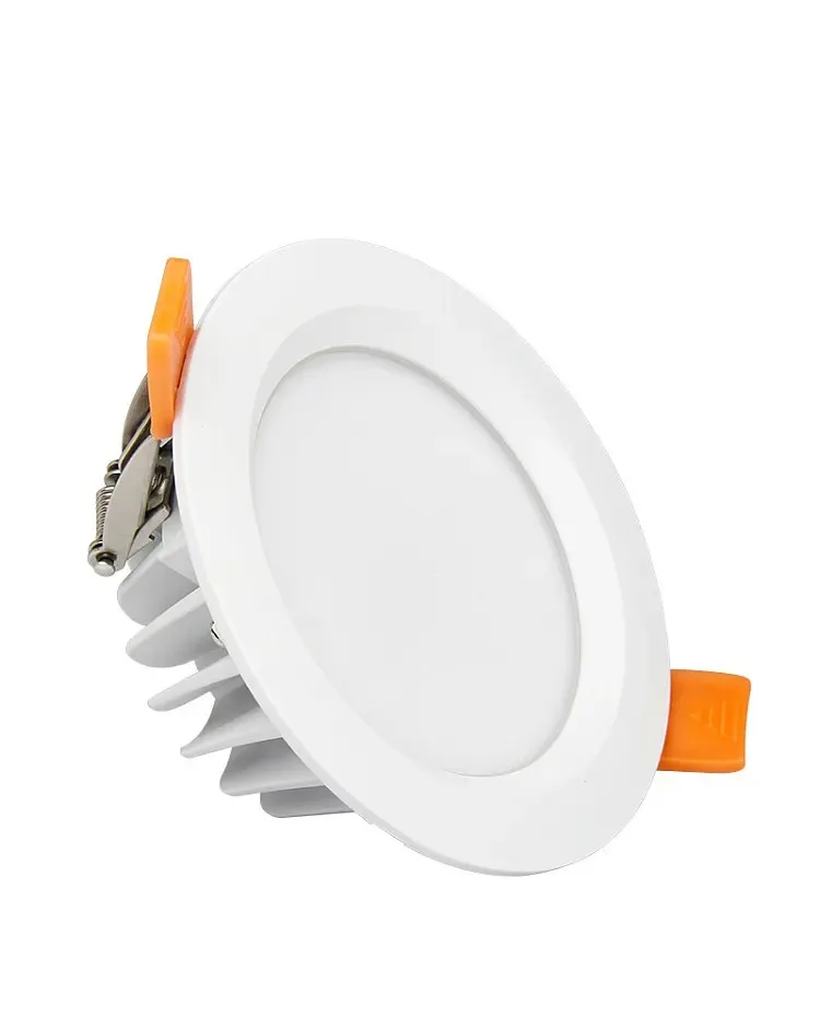
6W RGB+CCT Waterproof LED Downlight Spot View productCHECKPOINT / 02
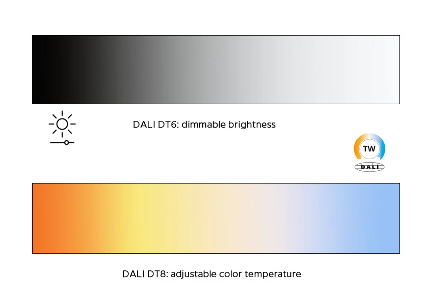
Match DT6, DT8 and the actual light engine
A single-channel dimmable load and a tunable-white or color-changing load may require different device types and command behavior. DALI-2 terminology, control gear type and certification status must be checked for the exact driver and controller; a product title that says DALI does not prove every mode is available. Keep CCT, RGBW, dimming range and feedback as explicit requirements.
- Single-channel dimming: confirm the driver and output behavior for the fixture.
- Tunable white or color: verify the device type, channel mapping and scene support.
- Do not infer interoperability from the connector or from the presence of a bus pair.
CURRENT PRODUCT RECORDS
6W RGB+CCT Waterproof LED Downlight Spot View productCHECKPOINT / 03
Plan the bus and mains separately
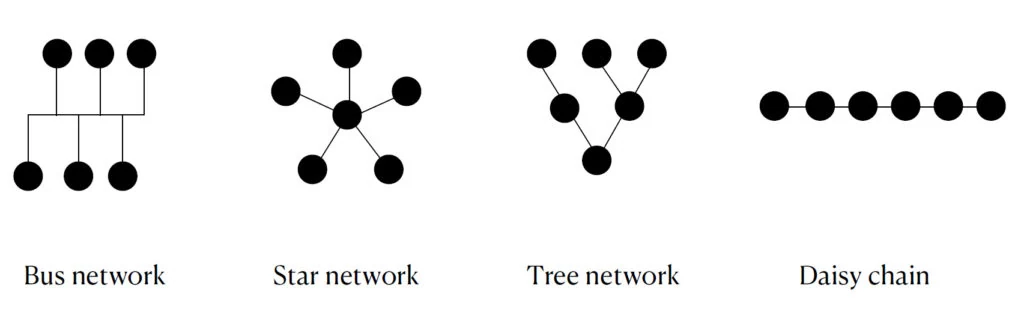
Draw the mains power path and DALI communication path as different layers, then review cable type, topology, polarity requirements, line length, voltage drop, bus power and protection against the selected equipment documentation and local electrical rules. Keep the bus within its system limits and make both the driver and bus connections accessible for service. A clean diagram names every control gear address, group and cable branch.
mains_path = supply -> DALI_control_gear -> light_engine
bus_path = DALI_controller -> control_gear + inputs
verify = cable + bus_power + voltage_drop + local_rules
CHECKPOINT / 04
Compare DALI with other control methods
Phase dimming changes the mains waveform and depends on compatible drivers. 0-10 V uses an analog control level and usually needs a separate power and status strategy. DMX is a fast channel-oriented control bus commonly used for show or architectural control. DALI is useful when addressed devices, groups, scenes and status feedback matter, but its value depends on the project scale, driver availability, commissioning skill and maintenance plan.
- Use phase control only with a driver specified for that method.
- Use 0-10 V when its one-way or feedback limits fit the design.
- Use DMX for the timing and channel model the project actually needs, not because it sounds more advanced.
CHECKPOINT / 05
Commission addresses, scenes and recovery
Before handoff, identify every control gear device, assign meaningful short addresses or groups through the selected commissioning tool, test each channel and record the final scene values. Check power-on behavior, minimum level, emergency or fallback behavior where applicable, sensor triggers and manual override. Keep a bus diagram, address list, driver revision and commissioning date with the project so a replacement device can be reintroduced without reverse engineering the ceiling.
discover -> identify -> address -> group
channel_test -> scene_test -> power_cycle
handoff = bus_map + device_list + scenes + recovery
CURRENT PRODUCT RECORDS
6W RGB+CCT Waterproof LED Downlight Spot View productVISUAL REFERENCES
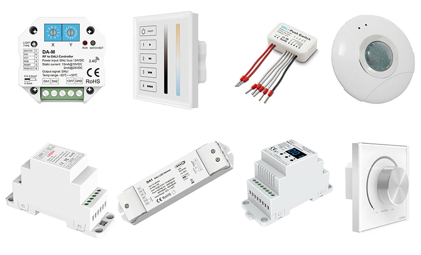
See the layers before you specify the parts.
FAILURE MODES
What usually goes wrong
- A DALI label is treated as proof that every fixture, driver and sensor will interoperate.
- The bus is drawn as a substitute for mains power to the LED driver.
- DT6 or DT8 behavior is assumed without checking the exact control gear.
- Addresses and groups are left undocumented after commissioning.
- The system is handed over without testing power-cycle, manual override or a replacement path.
TECHNICAL BASIS / VERSION
Keep the decision current
This guide is maintained as a versioned technical record. Recheck the current protocol documentation and the exact product revision before using it in a production installation.
Confirm the selected voltage, light engine, driver, controller, firmware and installation conditions against the product record and project brief.
FAQ / QUICK ANSWERS
Common questions about this lighting setup
Is DALI the same as a DALI dimmer?
No. DALI is a digital communication system. A working installation also needs compatible control gear or drivers, a bus, an application controller and a commissioning plan.
Can DALI control tunable-white lighting?
It can when the selected control gear and controller support the required device type and channel behavior. Verify the exact configuration rather than assuming a generic DALI label supports CCT.
Is DALI better than DMX or 0-10 V?
It depends on the job. DALI can suit addressed fixtures, groups, scenes and status feedback; DMX may suit fast channel-oriented show control; 0-10 V may suit a simpler analog path. Compare commissioning, wiring, scale and maintenance as well as the dimming result.
READING LIST
Reference points used for this guide
The page is rewritten for LumaCircuit readers. These references establish the original topic or technical context; they do not replace an exact product review or a LumaCircuit test record.
- Reference article / DALI bus, control gear and commissioning
- DALI Alliance overview