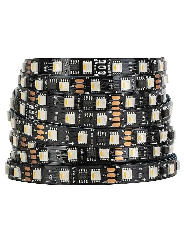
01 / Short answer
Voltage drop is a measurement problem before it is a product problem. Compare voltage at the source, branch and load end under the same known load, then fix the actual resistance bottleneck.
Installers and DIY builders troubleshooting dim ends, color shift, flicker or unexpected behavior on a long LED strip run
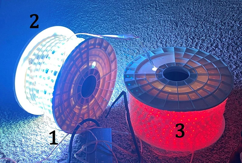
CHECKPOINT / 01
Recognize the symptoms without guessing the cause
A dimmer far end, color shift, flicker, controller reset or a strip that works only at low brightness can all indicate a power-path problem. They can also come from a bad connector, reversed channel, data fault, thermal protection or an underspecified supply. First reproduce the symptom at a repeatable brightness and record which section changes.
- Test the state that creates the problem, not only a soft white preview.
- Note whether the fault follows a branch, connector or strip section.
- Keep data and power troubleshooting separate for addressable products.
CHECKPOINT / 02
Measure voltage at the load
Use a meter at the supply terminals and at the strip input while the same known load is active. For a long run, add a far-end measurement and repeat the test at a connector, injection point or branch fuse when accessible. A no-load voltage reading can look perfect while the loaded reading exposes the loss. Observe polarity and use a safe measurement method for the selected voltage.
Vdrop = V_source_loaded - V_load_loaded
R_path = Vdrop / I_load
P_loss = I_load * I_load * R_path
CURRENT PRODUCT RECORDS
24 V WS2814 RGBW addressable LED strip View productCHECKPOINT / 03
Find every resistance in the path
The strip copper is only one part of the circuit. Cable length, conductor cross-section, solder joints, connectors, terminal blocks, fuses and small pigtails all add resistance. Current rises when brightness or channel count rises, so the same installation can appear healthy in a dim scene and fail at full white. Inspect warm connectors and discolored insulation as evidence of a local bottleneck, not as a reason to increase the supply voltage blindly.
- Measure both the positive and return paths where practical.
- Check the smallest connector and pigtail before replacing the whole strip.
- Record cable length, gauge, connector family, fuse and current for each branch.
CHECKPOINT / 04
Choose a remedy that preserves the topology
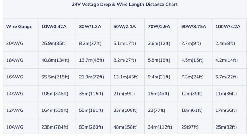
Shorter branches, parallel feeds, power injection, larger conductors, better terminals or a suitable higher-voltage strip can reduce loss when the product and layout allow it. Recalculate the current and protection for every change. A constant-current product needs its specified driver and load range; it is not a universal cure for a long constant-voltage strip, and an oversized supply cannot make a weak connector safe.
- Move high-current distribution closer to the load when the enclosure and service plan allow it.
- Inject at a planned point instead of improvising a second feed after the strip is hidden.
- Keep branch fuses and conductor limits aligned with the revised load.
CHECKPOINT / 05
Verify the repair under the original stress
After changing the cable, feed or injection plan, repeat the original bright-state test. Measure source and load voltage, inspect the far end, check temperature and run the intended colors or white channels. For an addressable system, also test data stability and controller recovery. Record the before-and-after values so a later extension does not erase the reason the repair worked.
before: state + current + V_source + V_load
change: cable | connector | feed | injection
after: same_state + same_measurements + temperature
CURRENT PRODUCT RECORDS
24 V WS2814 RGBW addressable LED strip View productVISUAL REFERENCES
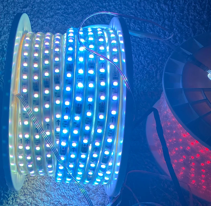
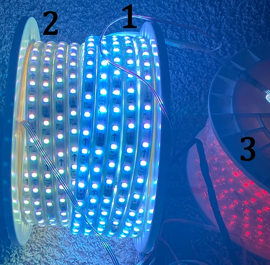
See the layers before you specify the parts.
FAILURE MODES
What usually goes wrong
- Voltage is measured at the supply with the strip switched off or dimmed.
- A large supply is installed while the connector or branch cable remains undersized.
- Only the positive conductor is checked and a high-resistance return path is missed.
- Power injection is added without a fuse, polarity record or new load calculation.
- The repair is accepted at low brightness and fails again when all channels are white.
TECHNICAL BASIS / VERSION
Keep the decision current
This guide is maintained as a versioned technical record. Recheck the current protocol documentation and the exact product revision before using it in a production installation.
Confirm the selected voltage, light engine, driver, controller, firmware and installation conditions against the product record and project brief.
FAQ / QUICK ANSWERS
Common questions about this lighting setup
How can I tell if an LED strip has voltage drop?
Reproduce the problem at a known bright state, then measure voltage at the supply and at the strip or far end while it is loaded. A meaningful difference points to loss somewhere in the cable, connector, protection device or strip path.
Does using a higher-wattage power supply fix voltage drop?
Usually not. A larger supply can provide more capacity, but it does not remove resistance in a cable, connector or strip. Check the loaded voltage and repair the bottleneck or redesign the branch.
Is 24 V always free of voltage-drop problems?
No. Higher voltage can reduce current for the same power, but every long branch still has resistance and a maximum run or injection requirement. Measure the exact installation under load.
READING LIST
Reference points used for this guide
The page is rewritten for LumaCircuit readers. These references establish the original topic or technical context; they do not replace an exact product review or a LumaCircuit test record.
- Reference / diagnosing LED strip voltage drop with loaded measurements