01 / Short answer
A single-color strip is electrically simple when the two conductors, supply voltage, current and branch layout are kept clear. Add a dimmer only on the low-voltage side when the dimmer is rated for the strip and the total load.
First-time installers and electricians planning a single-color low-voltage strip circuit
CHECKPOINT / 01
Start with the two-conductor interface
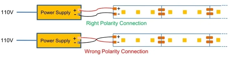
A single-color strip normally presents a positive and negative pad or lead. The marking on the PCB, the connector key and the power-supply polarity are the reliable references; red and black are common conventions, not a substitute for inspection. Confirm whether the strip is 5 V, 12 V or 24 V before connecting anything, because a visually identical board can belong to a different voltage family.
- Read the voltage printed on the strip, reel label or product record.
- Keep the cut end clean so both copper pads remain available.
- Use a meter to identify the DC output polarity when the supply markings are unclear.
CURRENT PRODUCT RECORDS
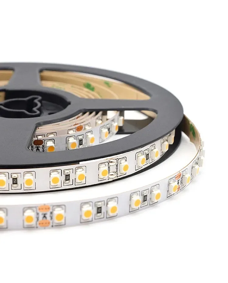
2835 flexible CCT LED strip View productCHECKPOINT / 02
Choose direct power or low-voltage dimming
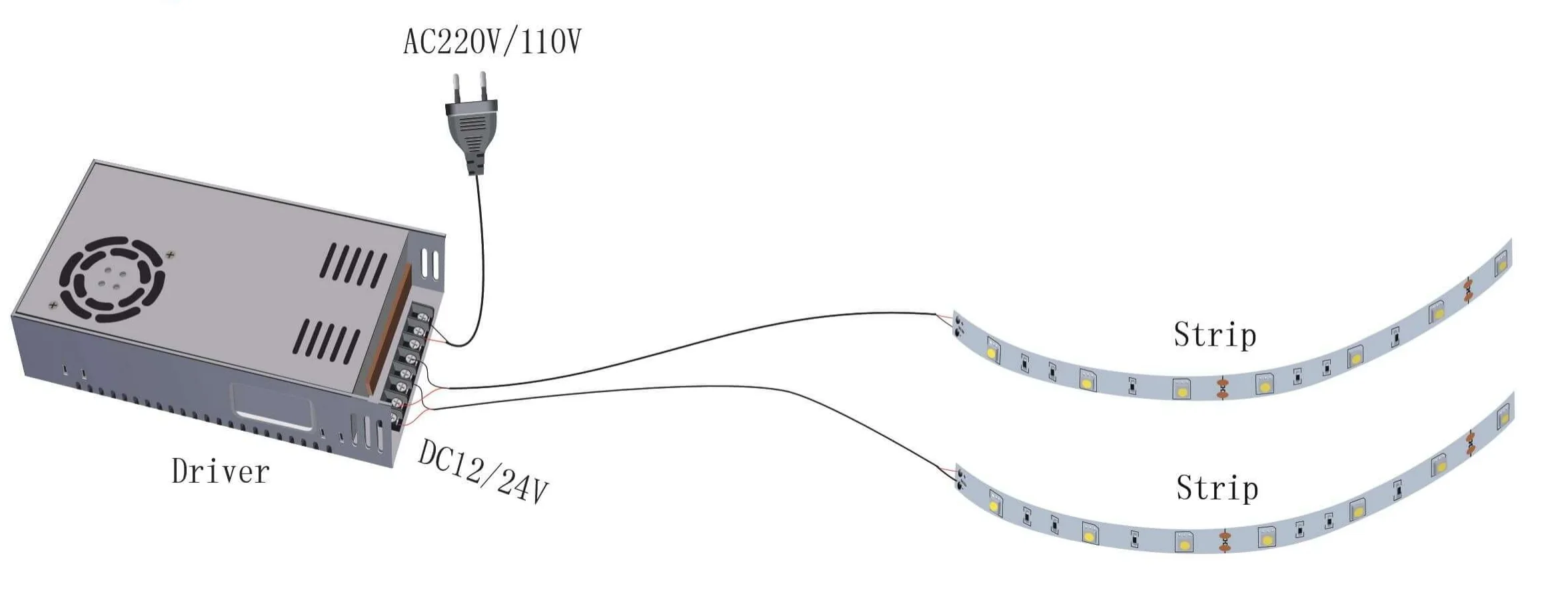
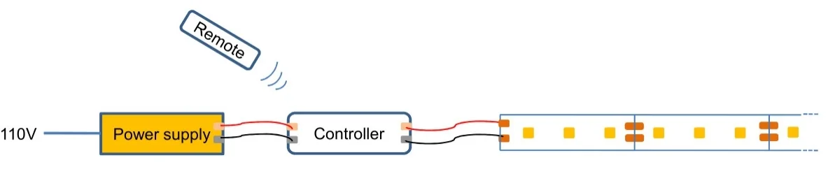
For a fixed-brightness installation, the strip can connect directly to a matched constant-voltage supply. For dimming, place a rated PWM dimmer between the supply and the strip, and size both the dimmer output and the supply for the full load. A wall switch on the AC side is not the same thing as a low-voltage dimmer and should not be used to control a DC strip unless the complete driver system is designed for it.
- Direct path: strip -> DC supply -> disconnect or switch.
- Dimming path: strip -> PWM dimmer -> DC supply.
- Do not place a low-voltage PWM device on the AC input terminals.
CURRENT PRODUCT RECORDS
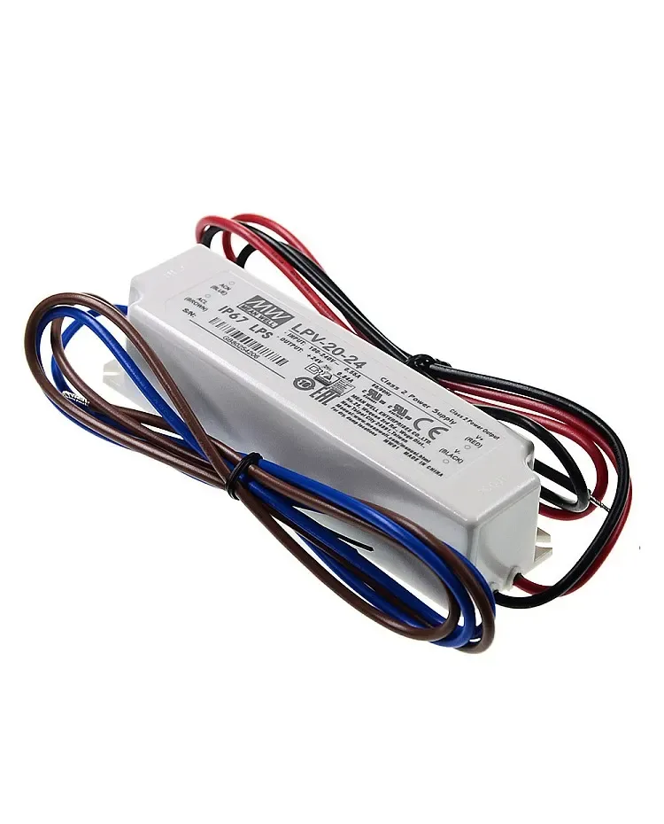
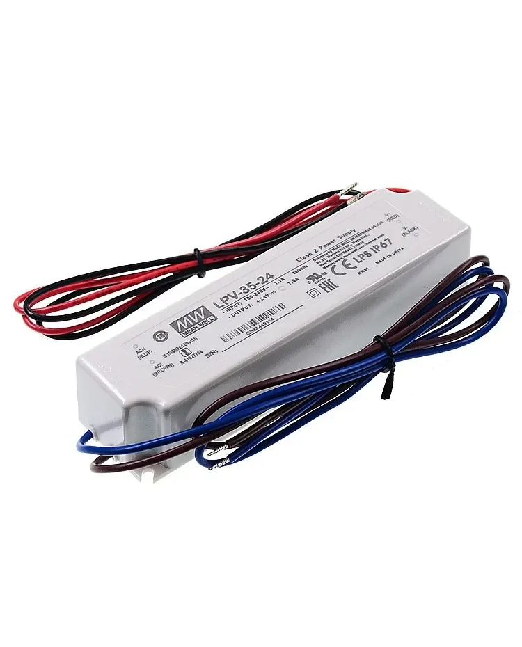
20 W 12 V DC waterproof LED power supply View product 35 W waterproof LED power supply View productCHECKPOINT / 03
Feed multiple strips as parallel loads
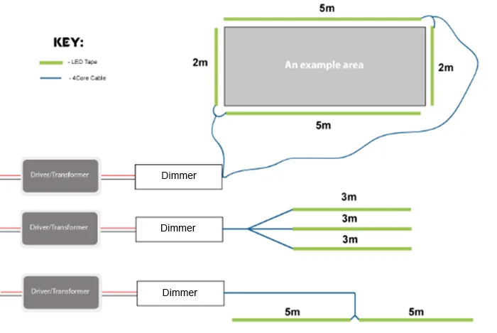
Several single-color strips may share one supply when the supply, distribution block, fuses, cable and dimmer can carry the combined current. Bring separate branch leads back to the distribution point where practical instead of using the first strip as a bus for every later section. Parallel wiring preserves the voltage plan, but it does not remove the need to calculate voltage drop on each branch.
total_load_w = sum(branch_watts)
supply_w >= total_load_w * 1.20
branch_current_a = branch_watts / voltage_v
CURRENT PRODUCT RECORDS
20 W 12 V DC waterproof LED power supply View product 35 W waterproof LED power supply View productCHECKPOINT / 04
Plan injection from the actual strip data
The allowable run is controlled by strip construction, watts per metre, copper, cable and the brightness level. A 24 V strip often supports a longer one-end feed than a 5 V strip, but no generic length replaces a loaded measurement. For a long shelf, cove or cabinet run, split the layout at the natural zones and feed each zone directly. Keep the controller or dimmer channel map aligned with those zones.
- Use the highest planned brightness for the voltage-drop check.
- Measure both ends of each branch after the strip reaches operating temperature.
- Leave a disconnect or service loop at every hidden junction.
CURRENT PRODUCT RECORDS
2835 flexible CCT LED strip View product 35 W waterproof LED power supply View productCHECKPOINT / 05
Test low, normal and full brightness
Before mounting the strip, inspect every joint and confirm the correct polarity with power removed. Energize at low brightness, then move through the intended range while checking evenness, flicker, connector heating and supply behavior. If several branches are controlled together, test them both together and independently. Photograph the final wiring and record the strip voltage, watts per metre, branch length, supply, dimmer and fuse.
- Verify the first and last LED section respond together.
- Check the dimmer minimum level for visible flicker or drop-out.
- Do not close the profile until the supply and joints can be serviced.
CURRENT PRODUCT RECORDS
2835 flexible CCT LED strip View product 20 W 12 V DC waterproof LED power supply View productVISUAL REFERENCES
See the layers before you specify the parts.
FAILURE MODES
What usually goes wrong
- The strip voltage is assumed from the plug or wire color.
- A low-voltage dimmer is wired to the AC input of a power supply.
- Multiple sections are daisy-chained past the voltage and current limits.
- A supply has enough nominal wattage but the branch cable or dimmer is undersized.
- The system is tested only at low brightness, so the full-load fault appears after installation.
TECHNICAL BASIS / VERSION
Keep the decision current
This guide is maintained as a versioned technical record. Recheck the current protocol documentation and the exact product revision before using it in a production installation.
Confirm the selected voltage, light engine, driver, controller, firmware and installation conditions against the product record and project brief.
FAQ / QUICK ANSWERS
Common questions about this lighting setup
Can a single-color LED strip connect directly to a power supply?
Yes, when the supply output voltage matches the strip and the supply has enough current with planning headroom. Confirm polarity, protect the branch and test the complete load before mounting.
Can one dimmer control several single-color strips?
It can when the dimmer output, supply, distribution, cable and fuses support the combined current. Separate branches are usually easier to diagnose than feeding one strip through another.
Why is one end of my strip brighter?
The usual causes are voltage loss in the strip, cable, connector or distribution point. Measure voltage at the supply and at the far end while the strip is at the planned bright state.
READING LIST
Reference points used for this guide
The page is rewritten for LumaCircuit readers. These references establish the original topic or technical context; they do not replace an exact product review or a LumaCircuit test record.
- Reference / wiring a single-color LED strip with a clean low-voltage path