01 / Short answer
Power injection is a branch design problem: calculate load, round-trip resistance and serviceable protection together. A supply with enough capacity does not prove that the cable, connector or branch is protected.
Builders extending a pixel or low-voltage strip run
CHECKPOINT / 01
Define each branch load before choosing injection points
Start with the exact variant: nominal voltage, declared watts per metre or maximum current, length that can be energized at once and the highest-consumption state. Divide the installation into named branches and record where each branch starts and ends. A typical length or a fuse value from another project is not a universal rule.
- Record the strip, IC, pixel grouping and operating state used for the load calculation.
- Calculate each branch separately when length, cable or connector changes.
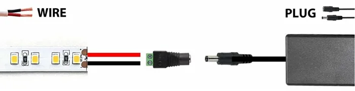
- Include pigtails, terminals and connectors among the parts that must carry the current.
branch_w = watts_per_m * energized_length_m
branch_a = branch_w / voltage_v
v_drop_v = branch_a * loop_resistance_ohm
v_load_v = v_source_v - v_drop_v
CURRENT PRODUCT RECORDS
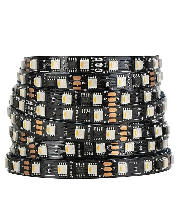
24 V WS2814 RGBW addressable LED strip View productCHECKPOINT / 02
Calculate voltage drop over the real current path
Resistance depends on conductor resistivity, total round-trip length, cross-sectional area and the contact resistance of every connection. A long cable with the same cross-section loses more voltage than a short one, and a small connection can become the hottest point. Measure voltage at the source and far end with the load connected; a general table does not replace this check.
- Count the positive conductor and negative return in the loop length.
- Compare source voltage, strip input voltage and far-end voltage in the same operating state.
- Check the final connector after installation, not only an open cable on the bench.
CURRENT PRODUCT RECORDS
24 V WS2814 RGBW addressable LED strip View productCHECKPOINT / 03
Separate the main fuse from branch protection
The main fuse limits the general output circuit according to the supply, feeder and complete assembly. A branch fuse limits that branch cable, connectors and pigtail. Its value must protect the conductor and the component with the lowest limit, considering allowable current, interrupt rating, polarity, enclosure and local requirements. The supply rating alone does not select a branch fuse.
- Place branch protection near the distribution point where the protected conductor begins.
- Document the reason for the selected value and the limit of every cable or connector.
- Keep mains work separate from the low-voltage assembly and follow local requirements.
CURRENT PRODUCT RECORDS
24 V WS2814 RGBW addressable LED strip View productCHECKPOINT / 04
Plan star distribution, injection and common ground
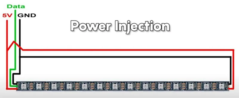
A star distribution can run each branch from one accessible point; injection can feed another point on the strip when the calculation requires it. Data continuity follows the product data input and output, while power continuity follows the positive and negative conductors. Preserve the common ground required by the controller, verify polarity and leave service loops so repairs do not require removing the finish.
- Label voltage, polarity, data, destination, length, cable and fuse at both ends.
- Do not inject power at the data output and do not assume a connector pinout is universal.
- Do not force all current through a small terminal just because the first section works.
CURRENT PRODUCT RECORDS
24 V WS2814 RGBW addressable LED strip View productCHECKPOINT / 05
Commission at maximum current and document recovery
Add branches one at a time and test full white or the highest-current state the system can request. Measure voltage and temperature at the supply, cable, pigtail, connectors and far end. Look for color shift, flicker, blackout or restart; then test controller restart, network loss and recovery after power is restored. Repeat the review if length, variant, enclosure or cable changes.
- Record measured current, voltage at both ends and temperature after the load stabilizes.
- Test each fuse behavior and leave a known manual recovery method.
- Hand over a diagram showing branches, polarity, data, protection and replaceable parts.
CURRENT PRODUCT RECORDS
24 V WS2814 RGBW addressable LED strip View productVISUAL REFERENCES
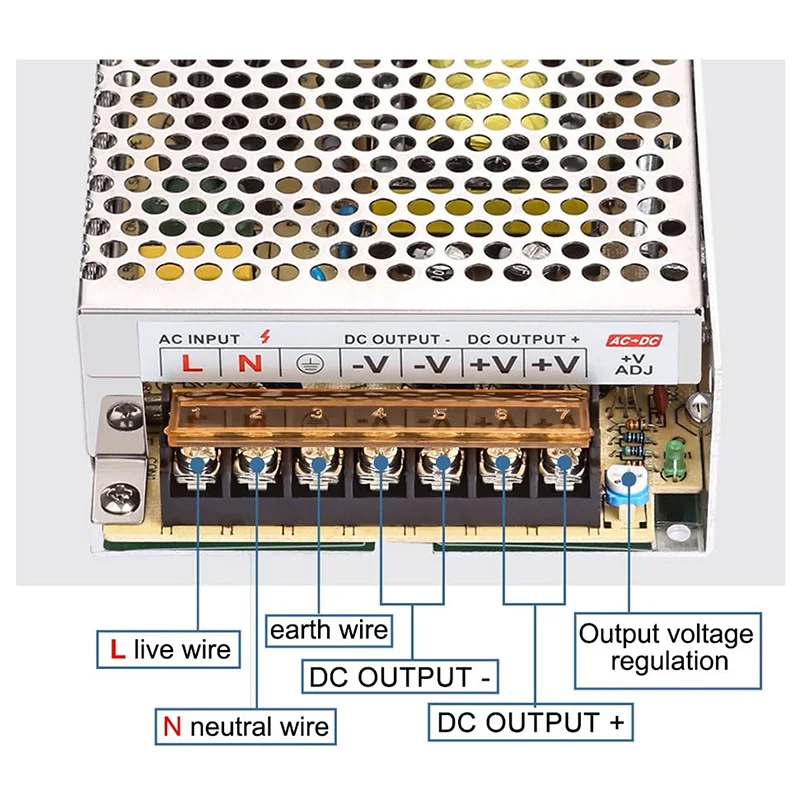
See the layers before you specify the parts.
FAILURE MODES
What usually goes wrong
- The supply rating is used as if it were the fuse for every branch.
- Voltage drop is calculated from the one-way length while return path, cross-section and contact resistance are ignored.
- Injection is added without checking common ground, polarity or data direction.
- A large cable or 24 V is treated as a guarantee for any length without measuring the far end.
- A short test section is approved without retesting full white, heat, flicker, fuses and recovery after expansion.
TECHNICAL BASIS / VERSION
Keep the decision current
This guide is maintained as a versioned technical record. Recheck the current protocol documentation and the exact product revision before using it in a production installation.
Confirm the selected voltage, light engine, driver, controller, firmware and installation conditions against the product record and project brief.
FAQ / QUICK ANSWERS
Common questions about this lighting setup
How do I choose a branch fuse value?
Start with the conductor and components the fuse must protect: cross-section, length, insulation, connectors, pigtails, interrupt rating and local requirements. Then check the normal load and fault behavior of the exact variant. There is no single value for every strip, length and connector.
Does power injection remove voltage drop?
No. It can shorten the current path for part of the strip and distribute the load, but cable, contact and strip resistance remain. Measure every branch at maximum load after all connectors are installed.
Can one supply feed several branches?
Yes, only when voltage, total load, distribution, feeder, cables, connectors, main fuse and each branch protection are designed together. A larger supply does not make an undersized branch safe or prove controller compatibility.
READING LIST
Reference points used for this guide
The page is rewritten for LumaCircuit readers. These references establish the original topic or technical context; they do not replace an exact product review or a LumaCircuit test record.
- Reference article / power injection, fusing and cable sizing