01 / Short answer
TRIAC dimming changes the AC waveform. An LED strip can use it only through a driver designed to accept the chosen phase-cut signal and produce the strip voltage. The dimmer, driver, minimum load, phase type and local electrical installation must be reviewed as one system.
Installers evaluating phase-cut wall dimmers for compatible LED drivers and low-voltage strip systems
CHECKPOINT / 01
Understand what the phase-cut device changes
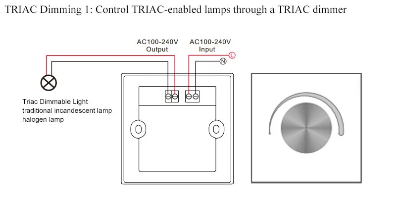
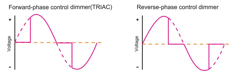
A TRIAC dimmer controls when current flows during each AC half-cycle, changing the power delivered to a compatible load. It is not a low-voltage PWM controller, and the dimmer output should not be connected directly to a 12 V or 24 V strip. The required boundary is mains dimmer -> compatible dimmable driver -> matched low-voltage light engine.
- Keep phase-cut mains work within local code and qualified installation.
- Confirm that the driver accepts the type of phase-cut signal.
- Never put a bare DC strip on a wall dimmer output.
CURRENT PRODUCT RECORDS
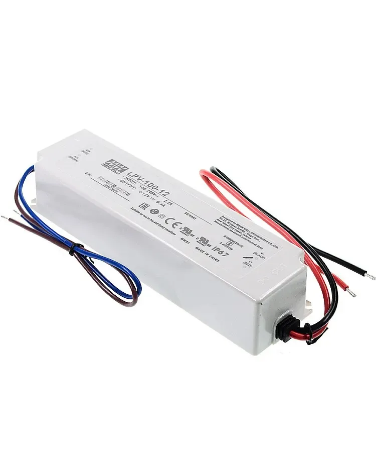
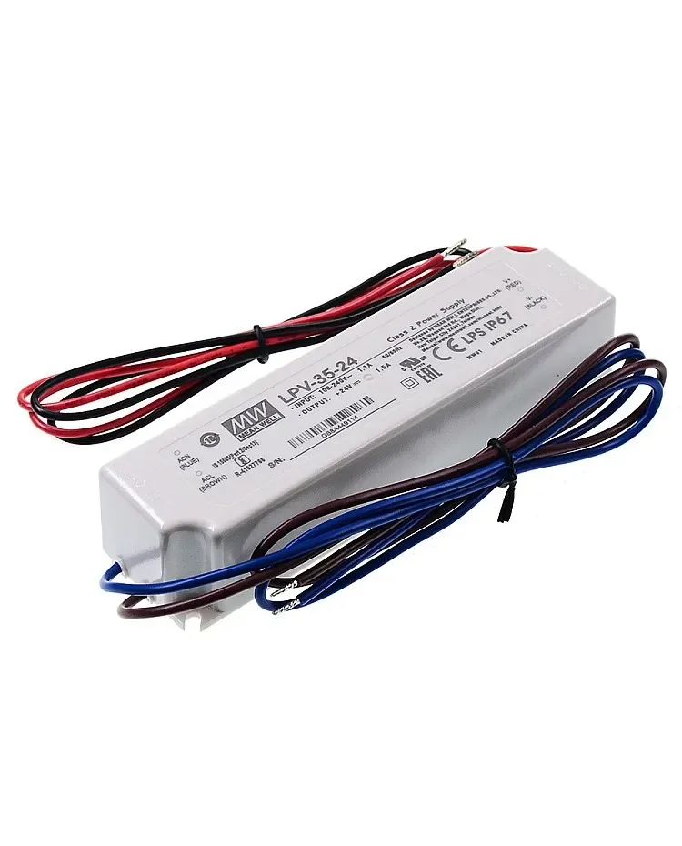
100 W IP67 LED power supply View product 35 W waterproof LED power supply View productCHECKPOINT / 02
Check leading-edge and trailing-edge compatibility
Leading-edge and trailing-edge dimmers shape different parts of the AC waveform and can produce different results with the same driver. LED loads may show flicker, buzzing, drop-out or a narrow dimming range when the pairing is wrong. The dimmer manual and driver manual should identify the supported phase type, minimum load and wiring method; a product photograph cannot establish any of these.
- Record the phase type and supported load range.
- Test the dimmer at the minimum, middle and maximum settings.
- Do not assume an incandescent-compatible dimmer is LED-driver compatible.
CHECKPOINT / 03
Match the driver to the strip and dimmer
The dimmable driver must provide the strip voltage and current while accepting the AC control method. The strip itself still needs a power and thermal plan, and a controller or PWM stage may sit on the DC side if the design requires color or channel control. Check whether the dimmer is controlling one driver or several, and keep the combined load inside every device rating.
- Verify output voltage and maximum current for the light engine.
- Check minimum load and inrush behavior with the full driver count.
- Keep a separate record for the AC device, driver, controller and strip.
CURRENT PRODUCT RECORDS
35 W waterproof LED power supply View product 100 W IP67 LED power supply View productCHECKPOINT / 04
Treat flicker, noise and EMI as acceptance criteria
A phase-cut system can behave acceptably on a bench and fail with a different load, cable route or dimming floor. Watch for visible flicker through a camera and by direct observation, acoustic noise from the driver, resets in nearby control hardware and unstable low-level output. These observations do not replace an electrical measurement, but they identify a system that needs a different dimmer, driver or minimum level.
for level in [min, mid, max]:
  set_dimmer(level)
  observe(flicker, noise, dropout, restart)
accept = stable_output && compatible_minimum_load
CURRENT PRODUCT RECORDS
35 W waterproof LED power supply View productCHECKPOINT / 05
Commission the mains and DC sides separately
With power removed, verify the AC wiring, protective devices, driver terminals and low-voltage polarity. Energize the driver with the dimmer at its approved starting position, then test the strip at several levels. Check the full run, controller behavior, loaded voltage, temperature and the defined off state. Record the dimmer and driver variants, phase type, load, minimum usable level and any brightness limit included in the handoff.
- Use a qualified person for mains installation and measurement.
- Confirm the driver enclosure and service access after the test.
- Do not release the wall plate as the only record of the dimming method.
CURRENT PRODUCT RECORDS
100 W IP67 LED power supply View product 35 W waterproof LED power supply View productVISUAL REFERENCES
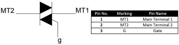
See the layers before you specify the parts.

FAILURE MODES
What usually goes wrong
- A TRIAC wall dimmer is connected directly to a low-voltage LED strip.
- Leading-edge and trailing-edge behavior is ignored when selecting the driver.
- The driver is compatible in voltage but outside its minimum load or dimming range.
- Flicker, acoustic noise or low-end drop-out is discovered only after the finish is complete.
- Mains and low-voltage wiring are mixed in one undocumented enclosure or cable path.
TECHNICAL BASIS / VERSION
Keep the decision current
This guide is maintained as a versioned technical record. Recheck the current protocol documentation and the exact product revision before using it in a production installation.
Confirm the selected voltage, light engine, driver, controller, firmware and installation conditions against the product record and project brief.
FAQ / QUICK ANSWERS
Common questions about this lighting setup
Can a TRIAC dimmer control an LED strip?
Only through an LED driver designed to accept that phase-cut signal and produce the strip voltage. A TRIAC dimmer should not be connected directly to a low-voltage strip.
Is TRIAC dimming always leading-edge?
No. Phase-cut systems can use leading-edge or trailing-edge behavior. Confirm the exact dimmer and driver pairing.
Why does a TRIAC LED system flicker at low brightness?
The dimmer and driver may have an incompatible phase type, minimum load or dimming range. Check the exact manuals and test the complete load across the usable range.
READING LIST
Reference points used for this guide
The page is rewritten for LumaCircuit readers. These references establish the original topic or technical context; they do not replace an exact product review or a LumaCircuit test record.
- Technical reference / TRIAC phase-cut dimming, drivers and commissioning