01 / Short answer
RGBW is four controlled channels, not RGB with a spare wire. Confirm the strip topology, voltage, common connection and controller current before extending the run.
Builders wiring a four-channel RGBW strip for ambient light, white light or a mixed scene
CHECKPOINT / 01
Separate RGBW from addressable RGBW
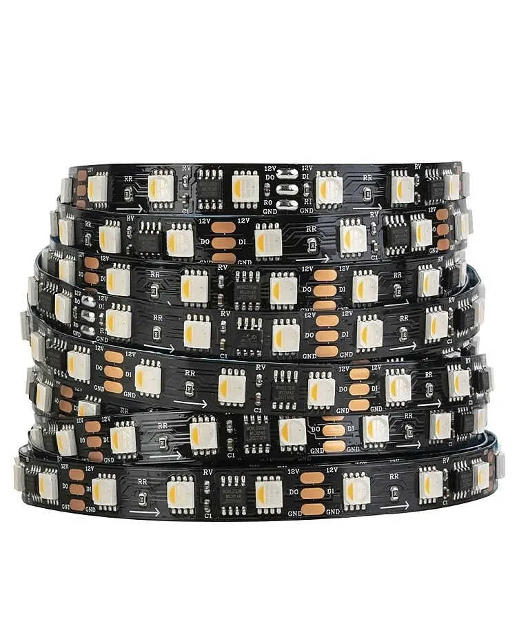
An analog RGBW strip exposes shared power and four switched channels; every section follows the controller output rather than receiving an individual data address. An addressable RGBW strip adds an IC and data path, so its signal, color order and controller profile are different. Read the selected product record before using a wiring diagram from another family.
- Analog RGBW: match four PWM channels and the strip voltage.
- Addressable RGBW: match the IC, data input, color order, pixel grouping and power.
- Do not let the number of visible colors decide the wiring topology.
CURRENT PRODUCT RECORDS
24 V WS2814 RGBW addressable LED strip View productCHECKPOINT / 02
Map the five electrical connections
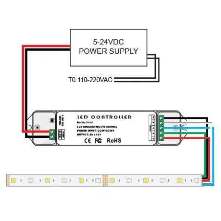
Most analog RGBW layouts have one common supply connection and separate R, G, B and W channel returns, but wire colors and connector order are not universal. Confirm the labels on the exact strip and controller, then check polarity with power removed. The white channel is an independent load and must be included in the controller and supply calculation.
channels = R + G + B + W
load_w = length_m * watts_per_m
current_a = load_w / voltage_v
controller_limit_a >= sum(channel_current_a)
CHECKPOINT / 03
Bench-test each channel before joining sections
Start with a short sample and a matched constant-voltage supply. Test red, green, blue, white and mixed output one at a time, then check the dimming floor and any channel that remains faint when it should be off. A reversed channel order can look like a software color problem, while a missing common connection can look like a dead strip.
- Photograph the known-good connector and label the common connection.
- Check the white channel at the same brightness used for everyday light.
- Keep power removed while changing channel order or connector wiring.
CURRENT PRODUCT RECORDS
24 V WS2814 RGBW addressable LED strip View productCHECKPOINT / 04
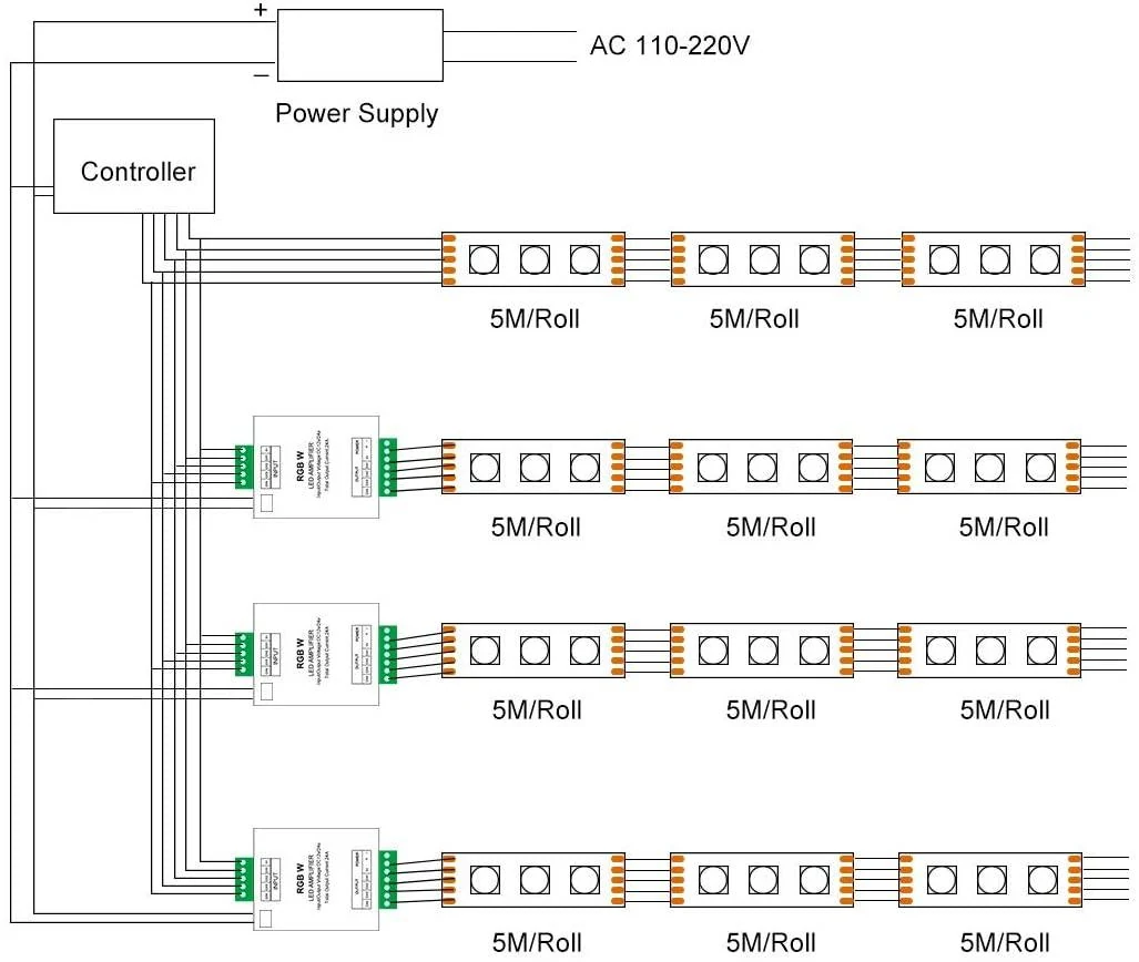
Extend branches in parallel, not by assumption
Several analog sections should receive the correct voltage through a distribution plan sized for their combined current. A controller or amplifier may be used for additional branches when its input, output, channel mapping and current limits are documented. Do not extend a long high-current strip through a small controller terminal simply because the first section works.
- Give long branches named cable, fuse and connector records.
- Recalculate the supply and controller load when a second section is added.
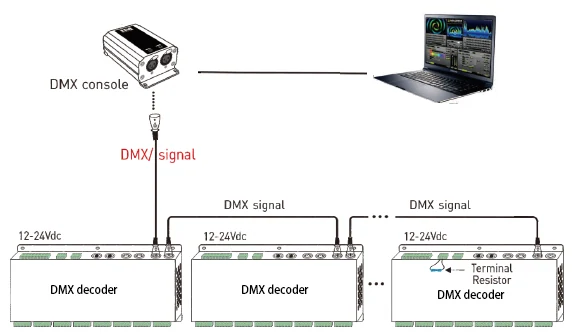
- Use a signal decoder or wired protocol only when it matches the selected analog light engine.
CURRENT PRODUCT RECORDS
24 V WS2814 RGBW addressable LED strip View productCHECKPOINT / 05
Commission color, white and service behavior
Test the full planned white state, saturated colors, mixed scenes and restart behavior before the strip is hidden. Measure voltage at the strip connection and inspect the last section for color shift or heat. Record the controller, supply, cable, fuse, connector order, strip variant and whether the installation is analog or addressable so a future repair does not start from a guess.
sample -> R/G/B/W_test -> polarity_check
full_white -> far_end_voltage -> temperature
handoff: topology + channels + controller + supply
VISUAL REFERENCES
See the layers before you specify the parts.
FAILURE MODES
What usually goes wrong
- A three-channel RGB controller is connected to a four-channel RGBW strip.
- The white channel is omitted from the maximum load calculation.
- Connector wire color is treated as a universal pinout.
- Several branches are daisy-chained through one small terminal without checking current.
- An analog RGBW strip is configured as an addressable product or vice versa.
TECHNICAL BASIS / VERSION
Keep the decision current
This guide is maintained as a versioned technical record. Recheck the current protocol documentation and the exact product revision before using it in a production installation.
Confirm the selected voltage, light engine, driver, controller, firmware and installation conditions against the product record and project brief.
FAQ / QUICK ANSWERS
Common questions about this lighting setup
What is the extra wire on an RGBW strip for?
It carries the dedicated white channel. The exact common connection and channel order depend on the strip construction, so follow the labels on the selected variant and match a four-channel controller.
Can RGBW strip sections be connected in series?
Do not use a series assumption for a long analog run. Plan each section as a correctly powered branch or use a documented amplifier or decoder architecture. The supply, controller, cable and branch protection all need recalculation.
Is an RGBW strip automatically compatible with WLED?
No. RGBW describes the light channels, not the controller protocol. An analog strip needs a compatible four-channel PWM path; an addressable strip also needs an identified IC and supported data profile.
READING LIST
Reference points used for this guide
The page is rewritten for LumaCircuit readers. These references establish the original topic or technical context; they do not replace an exact product review or a LumaCircuit test record.
- Reference / wiring RGBW LED strips with four-channel planning