01 / Short answer
A clean neon line depends on a matched internal width, bend direction, light engine and sealed termination. Cut and test each part before the sleeve hides the evidence.
DIY builders and installers assembling a flexible neon line from an LED strip, silicone sleeve and end treatment
CHECKPOINT / 01
Measure the internal cavity, not the outer tube
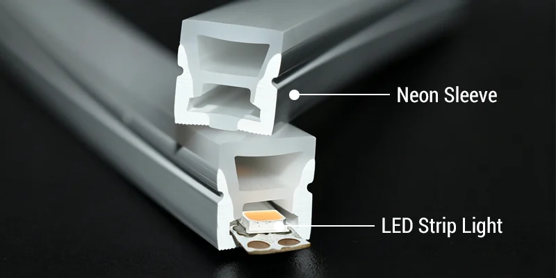
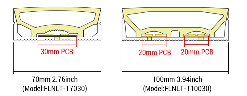
Neon sleeves and flexible profiles can look large from the outside while leaving a much narrower channel for the PCB. Record the usable width, height, bend direction, minimum radius, end-cap geometry and cable exit. The strip must fit without crushing the LEDs, while a loose fit can let the board rotate and point light away from the diffuser.
- Measure the actual cavity with the intended strip coating and solder joint included.
- Decide whether the sleeve bends on its top, side or full round axis.
- Leave room for the pull line, wire bend and end treatment.
CURRENT PRODUCT RECORDS
24 V side-emitting neon line, 6 × 12 mm View product 24 V side-emitting neon line, 10 mm View productCHECKPOINT / 02
Select the light engine and protection together
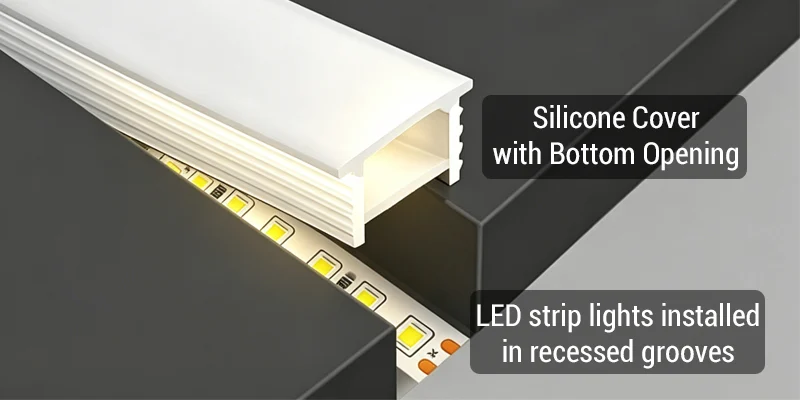
A fully enclosed sleeve can make an uncoated strip easier to insert and can leave more room for heat to move, but the sleeve, end caps, cable entry, adhesive and location must be reviewed as one environmental boundary. An open-bottom silicone cover is a different assembly and does not automatically make an indoor strip suitable for rain or immersion. Protection labels belong to the exact configured variant, not to the appearance of the silicone alone.
- For a sealed sleeve, verify the complete termination and cable path before using it outdoors.
- For an open-bottom cover, match the strip and channel to the actual moisture exposure.
- Do not stack coatings or sleeves without checking width, heat and bend behavior.
CURRENT PRODUCT RECORDS
Configurable 12 V silicone neon line View product 24 V IP67 CCT COB LED strip View productCHECKPOINT / 03
Cut the strip and sleeve before final assembly
Measure the finished length, cut the sleeve square and identify the strip cut marks before pulling anything into the channel. The cut interval, polarity, data direction and wire exit belong to the strip variant. Once the board is hidden, its marks are difficult to see and an on-site trim can damage an LED, resistor or seal. A short sacrificial sample is cheaper than repairing a finished line.
- Label the data input or positive end before the strip enters the sleeve.
- Use a sharp tool for a square silicone cut and remove loose debris from the cavity.
- Plan end-cap depth and wire strain relief before choosing the final cut length.
CURRENT PRODUCT RECORDS
24 V side-emitting neon line, 6 × 12 mm View product 24 V side-emitting neon line, 10 mm View productCHECKPOINT / 04
Pull gently and prevent rotation
A pull line is safer than forcing a long strip through the sleeve. Feed the line through the empty sleeve, attach it to the strip without stressing the copper or components, and have one person feed while another pulls slowly. Use the correct bend orientation and stop if friction, twisting or a snag develops. A strip that fits on a bench can still rotate during a tight installation bend.
- Keep the strip aligned with the diffuser face throughout the pull.
- Never drag a solder joint or connector through a cavity that was sized for the bare PCB.
- Respect the documented minimum bend radius and never fold the assembly into a sharp corner.
CURRENT PRODUCT RECORDS
24 V side-emitting neon line, 6 × 12 mm View product 24 V side-emitting neon line, 10 mm View productCHECKPOINT / 05
Seal, test and document the finished line
Terminate the cable, end cap and sleeve according to the selected assembly method, then allow sealants to cure before exposure. Test continuity, polarity, color or data direction, full planned brightness and the complete run for dark sections. Inspect the line while it is straight and while it follows the final bend. Keep a record of sleeve geometry, strip variant, cut lengths, controller, supply and termination method for the next repair.
- Keep the end cap removable only when the installation boundary allows it.
- Use a service loop rather than pulling the cable tight against the seal.
- Do not call the finished line weatherproof until the full assembly has been reviewed.
CURRENT PRODUCT RECORDS
24 V side-emitting neon line, 6 × 12 mm View productVISUAL REFERENCES
See the layers before you specify the parts.
FAILURE MODES
What usually goes wrong
- The strip width is matched to the outer sleeve dimension instead of the internal cavity.
- A loose strip rotates inside the sleeve and produces bright and dark faces.
- A waterproof coating is forced through a channel sized for a bare PCB.
- The assembled neon line is cut without exposing the strip cut marks.
- The end cap looks closed but the cable entry and adhesive cure were never checked.
TECHNICAL BASIS / VERSION
Keep the decision current
This guide is maintained as a versioned technical record. Recheck the current protocol documentation and the exact product revision before using it in a production installation.
Confirm the selected voltage, light engine, driver, controller, firmware and installation conditions against the product record and project brief.
FAQ / QUICK ANSWERS
Common questions about this lighting setup
Should an outdoor neon sleeve always contain a waterproof LED strip?
Not automatically. A fully enclosed and correctly terminated sleeve may use a different strip construction from an open-bottom channel, but the complete assembly must be reviewed for water entry, heat, cable exits and the actual location. A silicone appearance is not proof of an IP rating.
Can I cut a finished neon line on site?
Only when the configured assembly has a documented cut method and the strip marks remain accessible. In most builds, cut the strip and sleeve separately before final assembly so the electrical and sealing boundaries can be inspected.
Why does a loose strip create uneven neon light?
The board can rotate or move away from the diffuser face, especially in a round or tight-bending sleeve. The optical distance and direction then change along the run. A matched cavity and controlled pull are more reliable than filling extra space with force.
READING LIST
Reference points used for this guide
The page is rewritten for LumaCircuit readers. These references establish the original topic or technical context; they do not replace an exact product review or a LumaCircuit test record.
- Reference article / LED strips in neon sleeves