01 / Short answer
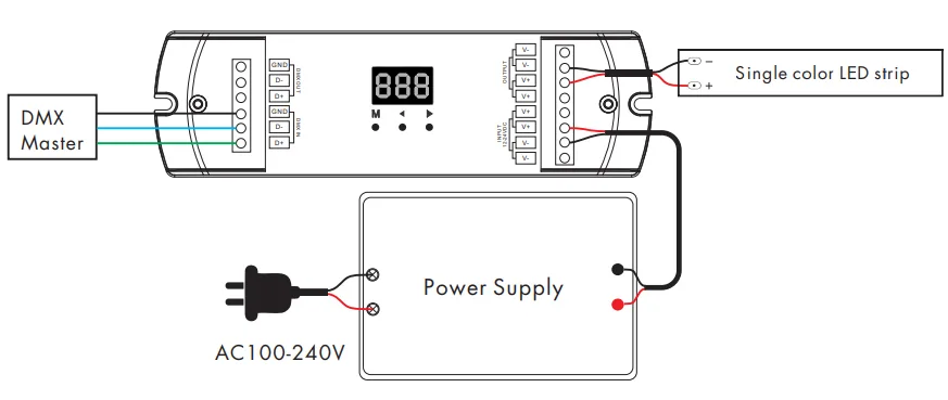
DMX is the control transport, not the LED strip itself. A complete system maps the controller output to a decoder or compatible digital strip, then maps channels to the light engine and power branches. Keep addresses, signal topology, power injection and recovery notes in the same record.
Show-control designers building DMX systems with analog RGB, RGBW, single-color or addressable LED strips
CHECKPOINT / 01
Choose the correct DMX output boundary
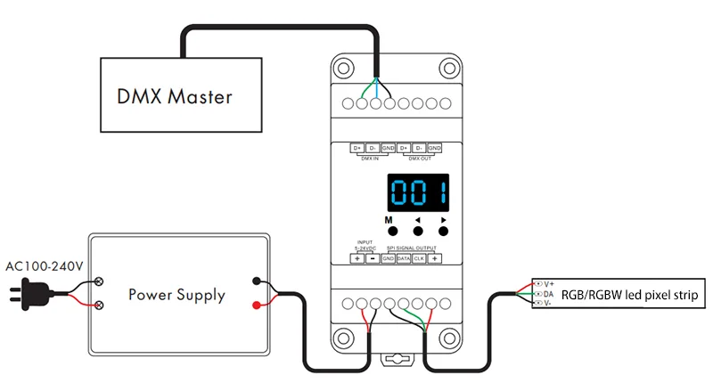
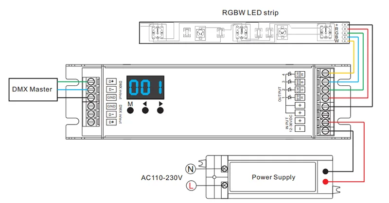
A DMX-capable fixture can accept the protocol directly, but an ordinary analog strip needs a DMX-to-PWM decoder and an addressable strip may need a DMX-to-SPI or compatible conversion stage. The decoder output must match the strip voltage, channel count and signal type. Do not connect a DMX pair to an analog RGB pad or assume that any digital strip understands DMX without an interface.
- Name controller, transport, decoder, light engine and supply separately.
- Confirm whether the output is PWM, SPI or a native DMX fixture input.
- Keep the exact addressable IC and color order in the light-engine record.
CURRENT PRODUCT RECORDS
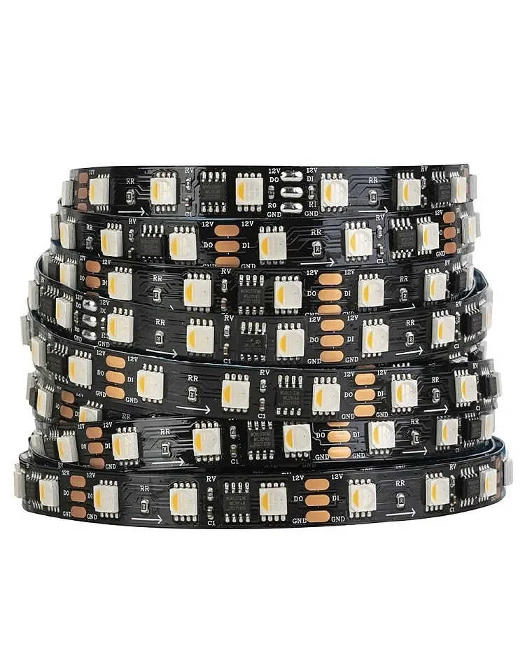
24 V WS2814 RGBW addressable LED strip View productCHECKPOINT / 02
Map addresses and channel counts deliberately
Each decoder or fixture needs an address range, and each range can represent a different number of channels. RGB, RGBW, CCT and RGBCCT arrangements use different channel maps; a digital decoder can also allocate channels by pixel group. Write the start address, universe, channel order, pixel grouping and fallback state in the handoff. A light that responds is not proof that its color or group mapping is correct.
- Reserve address space for every physical branch and future service unit.
- Label channel order at the controller, decoder and strip end.
- Test a single address before enabling the complete universe.
CURRENT PRODUCT RECORDS
24 V WS2814 RGBW addressable LED strip View productCHECKPOINT / 03
Build a readable DMX signal topology
DMX wiring needs a defined source, cable path, device order and termination strategy. Keep the signal path daisy-chained where the hardware requires it, avoid unplanned star branches and separate signal routing from high-current power conductors where practical. If a network gateway or Art-Net transport is used upstream, record the network, universe and node boundary separately from the physical DMX line.
- Use the cable type and termination method specified for the system.
- Document every decoder position and its address range.
- Keep a known-good short signal test lead for fault isolation.
CHECKPOINT / 04
Power the light branches independently
DMX carries control data; it does not supply the LED strip load. Size the DC supply, distribution, fuses, cable and injection points for the maximum state of each branch. An analog decoder can switch substantial current and an addressable strip can draw current across several groups, so channel count and power current need separate checks. Keep signal ground, power ground and protective boundaries documented for the selected hardware.
dmx_channels = decoder_map(universe, start_address)
branch_w = watts_per_m * branch_length_m
branch_a = branch_w / strip_voltage_v
verify(signal_path && branch_fuse && loaded_voltage)
CURRENT PRODUCT RECORDS
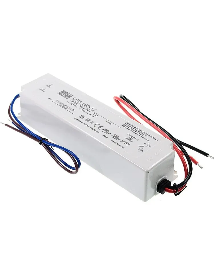
100 W IP67 LED power supply View product 24 V WS2814 RGBW addressable LED strip View productCHECKPOINT / 05
Commission one branch, then the show
Start with one controller, one decoder or fixture and a short strip. Verify address, color order, dimming, data direction, power polarity and the fallback state. Add branches one at a time, checking the DMX line, address ranges, loaded voltage, connector temperature and controller recovery after a power cycle. Record the tested universe, firmware or software version, decoder setting, termination, power layout and the exact limits of the installation.
- Test blackout, full white, color transitions and a communication loss.
- Check every branch from its local service point, not only from the console.
- Keep a manual recovery scene and a labelled disconnect.
CURRENT PRODUCT RECORDS
100 W IP67 LED power supply View productVISUAL REFERENCES
See the layers before you specify the parts.
FAILURE MODES
What usually goes wrong
- A DMX cable is connected directly to an analog strip or a digital strip with no compatible interface.
- Channel count, start address or color order is copied between different light engines.
- The signal is star-wired or left unterminated without checking the system requirement.
- DMX control is proven but the power branch, fuse or far-end voltage is not.
- A show preset is released without testing blackout, communication loss and power recovery.
TECHNICAL BASIS / VERSION
Keep the decision current
This guide is maintained as a versioned technical record. Recheck the current protocol documentation and the exact product revision before using it in a production installation.
Confirm the selected voltage, light engine, driver, controller, firmware and installation conditions against the product record and project brief.
FAQ / QUICK ANSWERS
Common questions about this lighting setup
Can DMX control any LED strip?
Not directly. Native DMX, analog PWM and addressable SPI strips need different interfaces. Use a compatible decoder or conversion stage and verify voltage, channels, signal and IC behavior.
Does DMX provide power to the strip?
No. DMX carries control data. The strip still needs a separately sized supply, cable, fuse, distribution and injection plan.
Do I need a terminator for every DMX decoder?
Termination depends on the physical DMX topology and the hardware guidance. Document the device order and use the specified termination at the end of the signal line rather than adding random branches.
READING LIST
Reference points used for this guide
The page is rewritten for LumaCircuit readers. These references establish the original topic or technical context; they do not replace an exact product review or a LumaCircuit test record.
- Technical reference / DMX transport, decoders, addressing and commissioning